Bad connections between the acceptor & the BATM mainboard account for 99% of intermittent acceptor problems you might encounter. This article describes what to look for.
The acceptor model we implement features extra (unused) wires for alternate connections.
Please do not tamper with these wires, they are deliberately disconnected and terminated.
Are any status LEDs illuminated on the acceptor head?
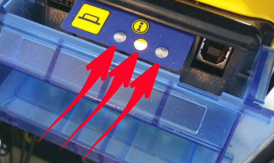
- YES: skip to Section B (data connections).
- NO: Proceed to Section A.
Section A: Power connections
This section describes bad connections causing power problems.
If any LED displays on the acceptor, skip to Section B (below).
1. Is the power supply LED on?
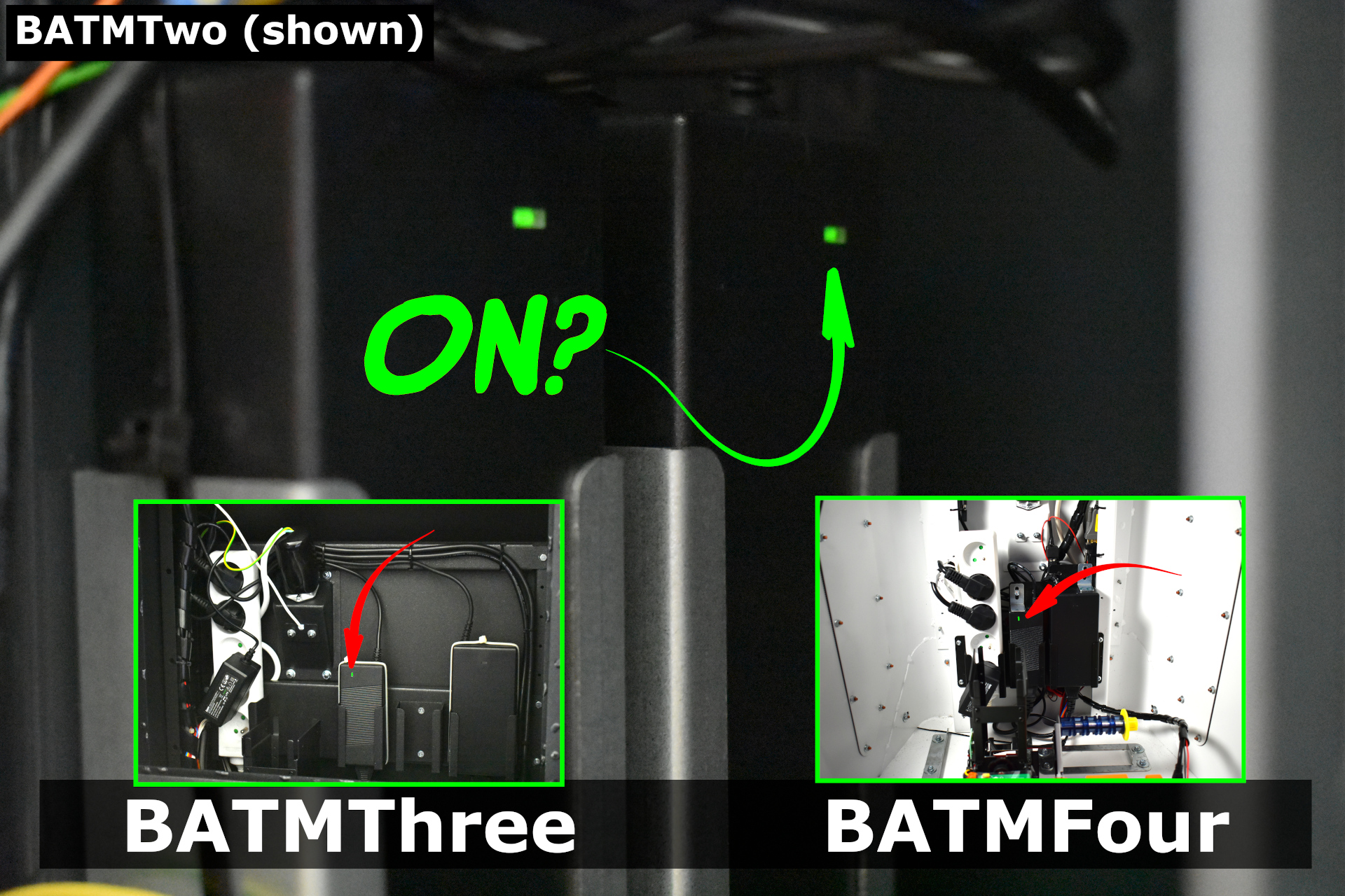
- NO, the LED is OFF: Proceed to Step 3.
- YES, the LED is ON: Proceed to Step 2.
2. Check the barrel connection:
Is it completely connected?

- YES, the barrel connector is connected properly. STOP. Please skip to Section C.
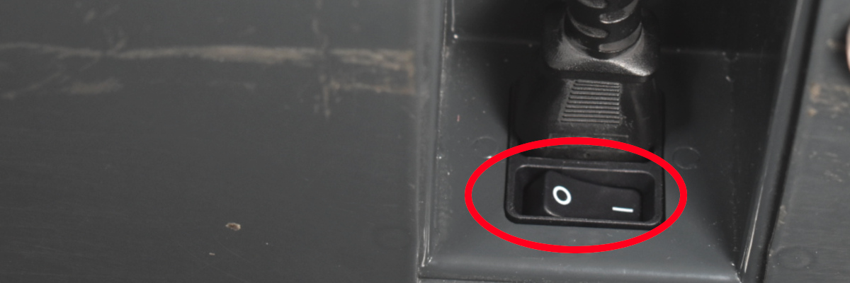
3. Check the power connection to the power supply.
4. Try another power source:
Remove power to the BATM.
Swap the power connector from another power supply to the acceptor power supply.
Reapply power.
Does the power supply LED light up now?
- NO: Create a Support Ticket to arrange for a replacement power supply.
- YES: Proceed to step 5 to check the power cable.
5. Check the internal power cable integrity.
BATMTwo: STOP! You cannot proceed further. Create a Support Ticket
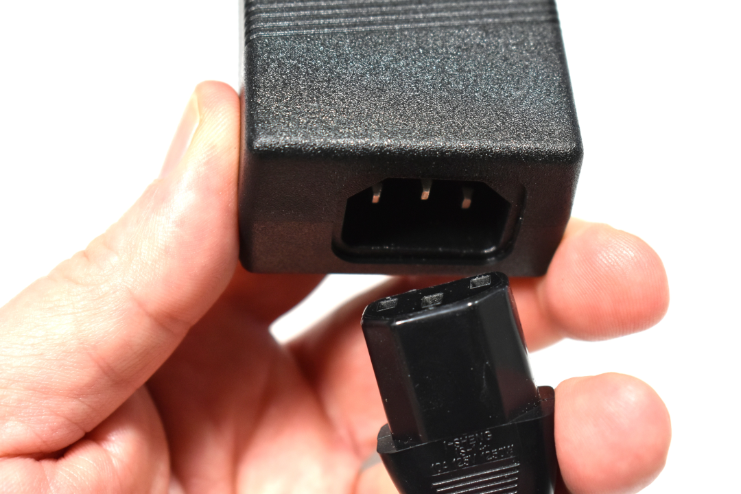
The power cable used is a standard (European CE 7/7) computer/monitor power supply cord.
Swap a power cable from another internal device to confirm the cable is defective.
If the cable is indeed defective, please Create a Support Ticket to order a new cable.
6. Try another outlet in the internal power strip / distributor.
If another outlet works, you can safely use that, or:
Please Create a Support Ticket to order a power distribution strip.
Section B: Data Connections
1. Turn the BATM OFF.
DO NOT PROCEED UNLESS THE POWER HAS BEEN DISCONNECTED!
2. Check the DB9 connection at the mainboard.

Check that the screws are hand-tightened (not too tight!).
3. Check the EBDS connector.
The other end of the DB9 cable (step 2) leads to a EBDS connector near the acceptor assembly.
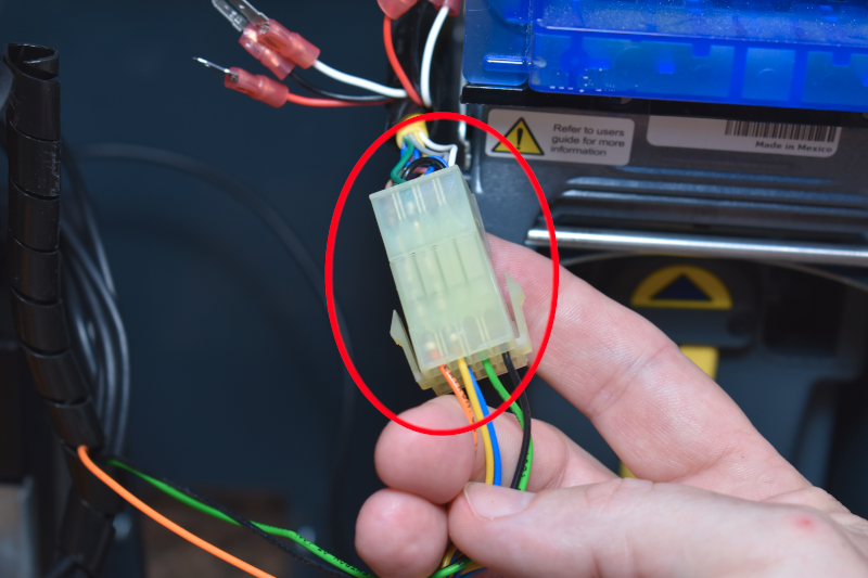
Check that the connector is completely together.
Check that the pins of the EBDS connector are all INDIVIDUALLY seated:
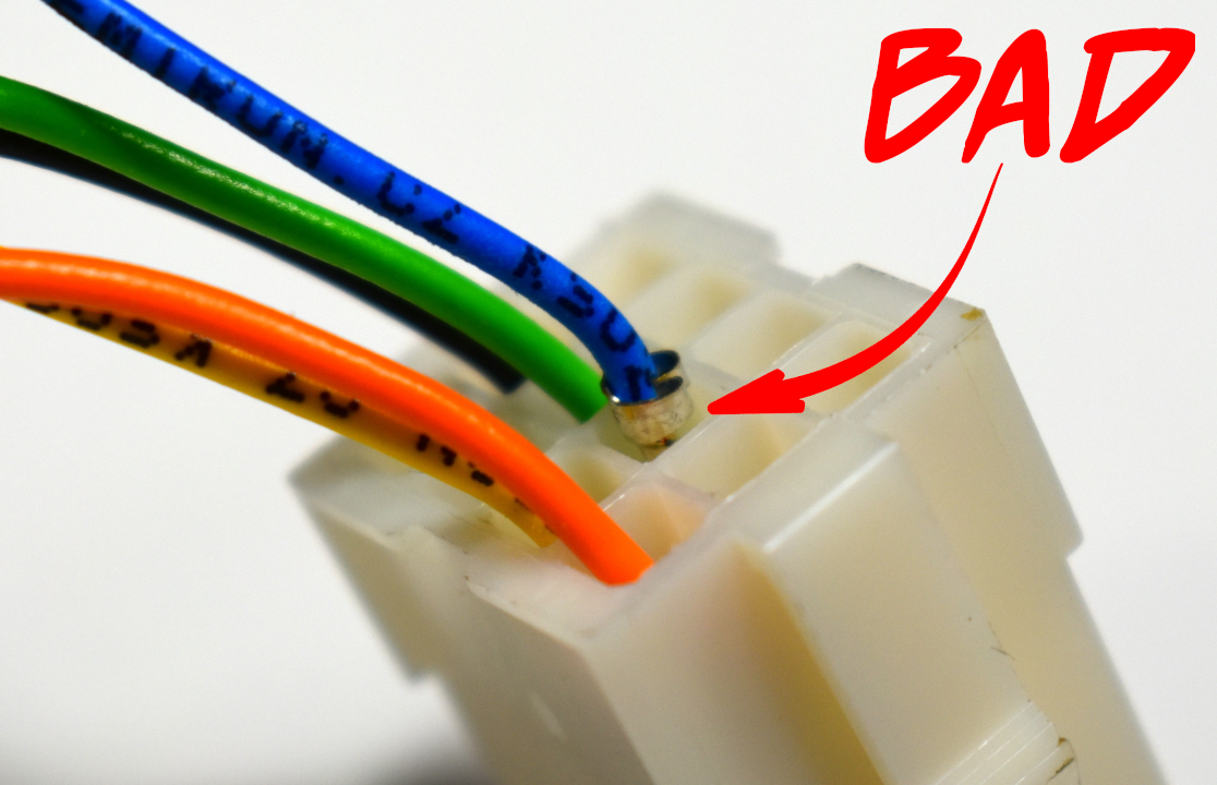
One bad pin is all it takes to cause your intermittent headache.
4. The EBDS connector cable ends at the acceptor assembly.
Move on to Section C.
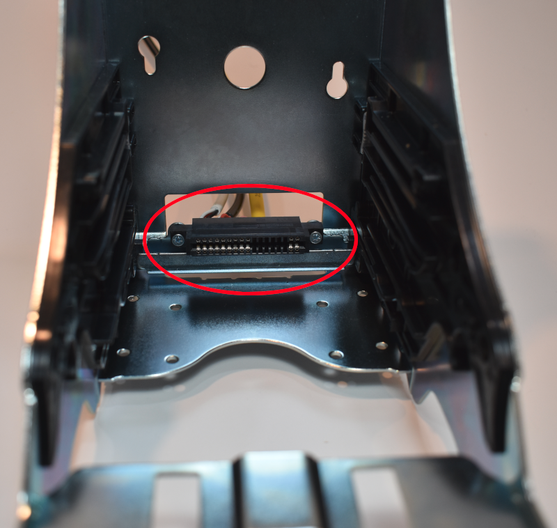
Section C: the Acceptor Assembly:
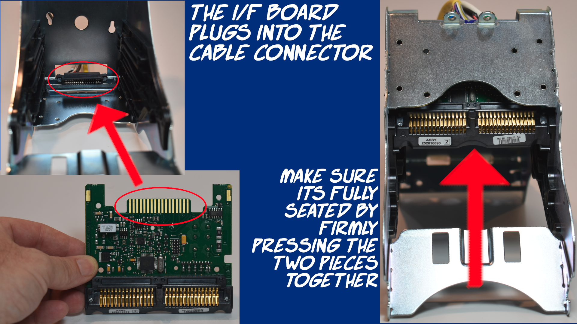
The interface (I/F) board slides into a connector at the back of the assembly. It’s possible for the connector to work loose during environmental temperature or humidity changes, not to mention routine use & handling, and vibrations while shipping. Many times a bad connection can be tracked down here.
DO NOT PROCEED UNLESS THE POWER HAS BEEN DISCONNECTED!
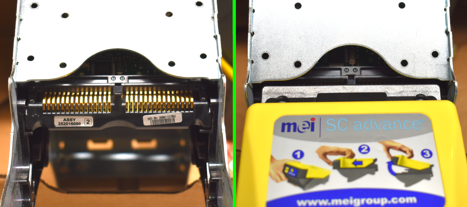
The acceptor interface (I/F) board slides into an edge connector:
The edge connector is hardwired to the EBDS connector (described in Section B).
The acceptor head slides onto the I/F board contacts:
- If all contacts are good, and the problem persists, you will need to Create a Support Ticket
Please include:
pictures of all described connections,
a screenshot/picture of the BATM administration screen,
a short, small video (under 20mb) of the acceptor LED’s (10 seconds+),
a second video demonstrating the problem with the acceptor.